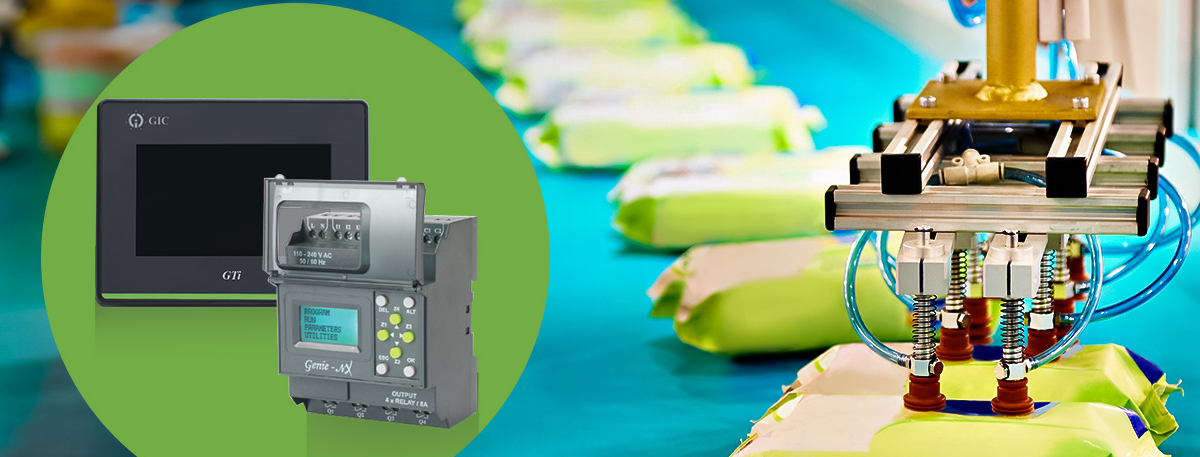
How do HMI and PLC interface each other?
The interaction between Human-Machine Interfaces (HMI) and Programmable Logic Controllers (PLC) involves both hardware and software components to facilitate communication and control within industrial automation systems. Here’s a more detailed breakdown of their interface:
1. Hardware Connection:
a.Communication Ports: Both HMI and PLC devices have communication ports or slots for various communication modules. These modules enable them to connect to each other through specific communication protocols (e.g., Ethernet, RS-232, RS-485, Profibus, Modbus, etc.).
b.Wiring and Cabling: Physical connections between the HMI and PLC are established using appropriate cables or network infrastructure based on the chosen communication protocol. This enables the exchange of data between the devices.
2. Software Communication:
a.Protocol Configuration: Within the HMI and PLC programming software, engineers configure the communication settings such as baud rate, parity, data bits, etc., to ensure both devices speak the same language (compatible communication protocol).
b.Tag or Variable Mapping: Engineers define and map tags or variables in the HMI software that correspond to the data points in the PLC. These tags represent information such as sensor readings, control signals, status indicators, etc.
c.Data Exchange: Once configured, the HMI software reads and writes data to/from the PLC based on these mapped tags. It sends commands, reads sensor values, and receives status information from the PLC, allowing real-time monitoring and control.
3. Functionality and Interaction:
a.HMI Visualization: The HMI software is responsible for creating graphical representations of the automation system. It generates screens, displays data, and provides interactive elements like buttons, sliders, and input fields for user interaction.
b.PLC Logic Control: The PLC contains the control logic programmed by engineers. It reads inputs from sensors, executes programmed logic, and sends outputs to actuators or other devices. The HMI communicates with the PLC to request information or send control commands based on user interactions.
c.User Interface (UI): The HMI’s UI allows operators or engineers to interact with the system. They can monitor processes, change set points, acknowledge alarms, initiate sequences, and more, sending these instructions to the PLC for implementation.
4. Error Handling and Diagnostics:
a.Alarms and Alerts: Both HMI and PLC systems can generate alerts or alarms. The HMI displays these notifications to operators, providing information on faults or abnormal conditions detected by the PLC.
b.Troubleshooting: Operators use the HMI to diagnose issues by accessing detailed system information, error logs, or diagnostic tools provided by the HMI software. This aids in identifying and resolving problems within the automation system.
In summary, the HMI and PLC interface involves configuring communication protocols, establishing hardware connections, mapping data points, enabling control and monitoring functionalities, and providing a user-friendly interface for operators to interact with the automated system while the PLC executes the programmed control logic.


